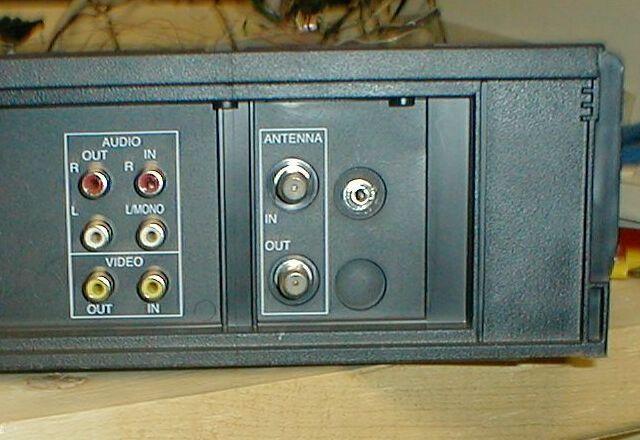
The Pioneer SR Control In/Out Jacks
There is a pair of 3.5 mm jacks on the back of my Pioneer receiver. One is a "control in" jack, and the other is a "control out". My Pioneer DVD player also has a "control in" jack.
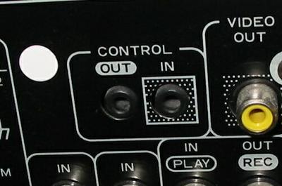
The idea is that you can link all your Pioneer equipment together so that they can control each other. If I connect the receiver's "control out" jack to my DVD player's "control in" jack, the DVD player responds to remote contol signals via the "control in" jack instead of via its built-in IR sensor. This is especially cool when the controlling unit and the controlled unit are in different rooms. It's like a wired version of an IR repeater system. Plugging into a control jack on the back of the unit is a lot cleaner than sticking an IR emitter to the front of your equipment.
Control Jack Electrical Interface
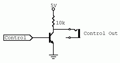
To find out what kind of circuit was on the other side of the recever's "control out" jack, I plugged a 3.5 mm mono plug into the jack and hooked it up to an oscilloscope. There was about five volts of output on the tip line when it was idle. I pointed a remote at the receiver and pressed a button. I saw a train of zero volt pulses, which look a lot like what comes out of those Sharp IR receiver modules. Those modules have an open collector output and a pull-up resistor. I suspected that the control jack was the same. To find out, I attached a pull-down resistor between the control out jack and ground. The control jack's voltage went down. I found that with a 10K pull-down resistor, the "control out" voltage was about half of its normal five volts, so I know that the internal pull-up resistor was the same. I also found that the internal pull-up resistor for the "control in" jack was around 100K.
Interestingly enough, it doesn't look like the outer ring of the control jacks are grounded. I had to find a ground somewhere else on the receiver, like one of the RCA jacks.
Control Jack Protocol
I suspected that the control signal was just a demodulated version of the IR signal coming from the remote. To prove it, I hooked channel one of my scope to the tip line of the "control out" jack and channel two of the scope to the output of a Sharp IR receiver module. I pointed a remote at both units and pressed a button. Both channel one and channel two showed the same signal. I also found that the "control out" jack repeats the signal from any remote I pointed at the unit, not just my Pioneer remote. This is all very good news.
The Mitsubishi VCR
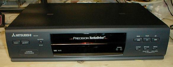
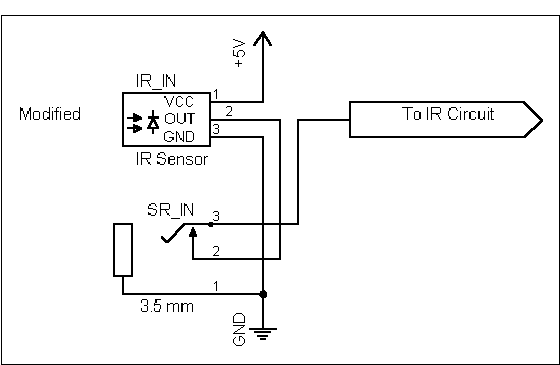
I have a Mitsubishi HS-U447 VCR that has no control jacks at all. I figured that all I needed to do to add a jack would be to wire a closed-circuit type of 3.5 mm mono jack in series with the built-in IR sensor. I opened up the VCR and found the sensor. It had the usual three leads. A volt meter showed one lead at zero volts, and the other two were around five volts. So, one of the five volt leads was the output, which is normally high. The scope showed me which one it was. Also, the volt meter, when set to AC volts, showed me an AC voltage on the output when I pressed a button on the remote.
After some probing around with an ohm meter, I found that the output of the IR sensor went to a nearby resistor. I cut one lead of the resistor and connected the 3.5 mm closed-circuit type jack in series with the sensor's output and the resistor. The jack is wired in such a way where the IR sensor will be connected to the resistor if nothing is plugged in. If something is plugged in, then the tip of the plug will be connected to the resistor, and the IR sensor will be disconnected.

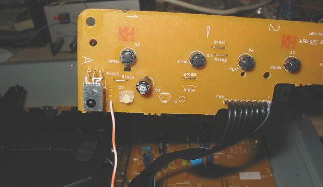
Here are the wires soldered onto the sensor output, the resistor, and a ground point.
As for where to put the jack, I found a convenient spot on the back of the VCR and drilled a hole just large enough for the jack. Fortunately, the back panel of the VCR was plastic, so it was easy to drill.

Testing The New "Control In" Jack
First, I plugged nothing into the jack and used the remote with the VCR to make sure it still worked. Next, I plugged one end of a cable into the new jack and left the other end of the cable unattached to anything. I tried the remote again and made sure that it didn't work anymore, since the plugged-in cable should be overriding the internal IR sensor. And last, I plugged the other end of the cable into the Pioneer receiver's "control out" jack and tried the remote again, this time pointing it at the receiver. All worked well. Keep in mind that since the ring of the receiver's "control out" jack isn't grounded, you have to ground the VCR to the receiver another way, like with the video and audio cables.
And now, two pieces of AV equipment which were never meant to be attached are playing well together.
The JVC DVD Player
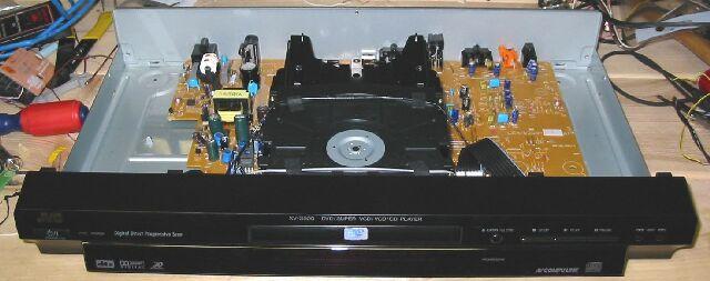
I also have a JVC DVD player that could use a "control in" jack too. This player is very new, and I don't feel like drilling holes in its metal case to add a 3.5mm jack. I might change my mind in a year or so, but not today. I took it apart and looked at it for a while, and then I got an idea...
Now, when I start telling you about this, you're probably going to think, "John, you're an idoit. You're going to blow up your equipment." But, think about it for a while first. If you still think I'm an idiot, just send me email and tell me why. Perhaps there's something I haven't thought of.
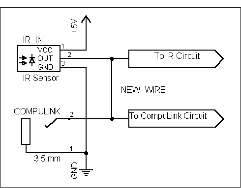
This DVD player has two 3.5mm jacks on the back already for AV CompuLink. I already checked, and it looks like the CompuLink protocol is not an unmodulated version of the IR signal. Too bad. But, both the CompuLink signal and the IR sensor signal look like they both have the usual open collector output. Hmm, I could just wire the IR sensor output and the CompuLink jack together. Yeah, the CompuLink input will be getting the IR signal, and yeah, the IR input will be getting the CompuLink signal, but I'm hoping that each input ignores signals that it doesn't understand. Of course, wiring it up this way will cause the jack to be not only a "control in" jack, but also a "control out" jack. Whatever signal the internal IR sensor picks up will be sent out the jack. I'll just have to keep this in mind. It might even be useful in the future.
So, here's the board that has the IR sensor, as well as some of the front panel buttons.
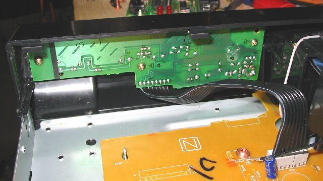
I unscrewed the board and looked at the other side. You can see the IR sensor. You can also see that there is an extra set of holes for what might be a different kind of sensor that's not used. I found the hole that's connected to the sensor's output and soldered a wire to it.
I then soldered the other end of the wire to the CompuLink jack's tip connection. That's it. I'm done. No parts were cut, and no new holes in the case were drilled.

Testing The "Control In/Out" Jack
I tested this one pretty much the same way I tested the Mitsubishi VCR by hooking it up to my Pioneer receiver's "control out" jack. I also tested both the DVD player and the VCR together by connecting their control jacks together. I could control the VCR by going through the DVD player's IR sensor, out its control jack, and into the VCR's control jack.

Right now, these two guys are hooked up a pair of modulators which are distributed to all the TVs in the house. Also, near each one of the TVs is an IR sensor that's wired into a control bus, which is connected to both of these units. I can control the VCR or the DVD players from any room with a TV. It seems to work great, and I haven't blown anything up... yet.
Naming These Jacks
These remote control jacks behave differently depending on how they are wired. It would be nice if I labeled them so that I know what kind of jacks they are. Since I don't know of any standard naming method, I'll make up my own. I'll prefix the name with RC- for remote control. Then there will be one or more qualifiers which will tell you what kind of remote control jack it is. I'll use these:
- I - Jack accepts remote control commands as input
- O - Jack outputs remote control commands
- X - Plugging into this jack disables the internal IR receiver
There are only several combinations that even make sense, and I'll give you two examples of the ones I think are most useful. The first is the RC-IX jack. It will accept remote control commands as input. It does not work as an output. Plugging into this jack disables the internal IR sensor. It is wired like this:

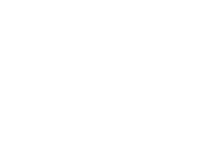
Another one that is easy to implement is the RC-IO jack. It allows the unit to accept commands via this jack. Also, any IR commands that get picked up by the unit's internal IR sensor get sent out this jack. It is wired like this:
So, when would you want to use an RC-IO jack? Well, I can think of one use, and that's when you would combine it with an RC-IX jack, like this:
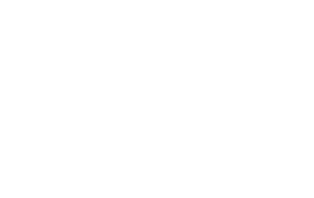
So, you could have your control line going into the RC-IX jack on one unit. Then, if you want to control a second unit, you would plug in a cable between unit one's RC-IO jack into unit two's RC-IX jack.
The wiring for an RC-I jacks is a little trickier, because you want to accept input, but have no output, and you don't want to disable the internal IR sensor. You would need some sort of buffer to allow the signal to pass only one way. The same is true for RC-O jacks. Maybe a simple diode would work. I'll leave that up to you.
posted by John Sevinsky @ 8:02 PM
18 comments
![]()

18 Comments:
That's a great hack. I don't have a Pioneer stereo now, but my mother had one when I was a kid, and I could never figure out what those jacks in the back were for! (She had me (10 years old) hooking up the stereo.)
This is tooo cool. I have only one entertainment system right now, but I've been fiddling with the idea of running wires up to my computer upstairs. It would be really cool to be able to not only control the receiver but also the VCR and DVD player by recording the signals for the different command as functions in a delphi programs.
Thanks for the idea!
Nice work. Thanks for the excellent documentation of your explorations.
Wow, inpressive experiment. I have these jacks on my pre-amp and amp and was just looking for the correct cable to attach them. So any 3.5mm mono cable will work?
Hello, in my Hi-Fi kit I have a CD player SANYO CP-59
On the back I discovered that 3-pin connector that says REMOTE SYSTEM. Because the player will work in conjunction with a tower JVC DR-E5L me and the synchronization system COMPU LINK so I wondered whether these two devices could not be To connect?? The towers are handled via command output jack 3.5 mm mono and there are two ones JACK therefore conclude that it is a command input - output. enter through a single jack into control commands to the CD player and the second is based commands to the CD player.
Is it possible to connect CD player SANYO CP-59 and Tower JVC DR-E5L? (Wired remote, through the RC tower JVC?)
REMOTE SYSTEM plug in the CD player Inside their description of the prince and those three are: CALL. S. AUTO. F. IR.
thanks for the advice.
http://yfrog.com/5djvcbackj
Good but not Best as this
http://www.hi-coder.com
Thanks, for the information; we will add this story to our blog, as we have an audience in this sector that loves reading like this”.
Remote equipment hire specialist
There are no tricks or hacking involved in audio chatting with your buddy on a pc it's just a matter of using a reliable service that has support for both operating systems.
Audio visual hire
The good idea
Excellent sleuthing work !
Quite some time on now from above comments, but I believe I can add value by stating the intention of the PIONEER version of the System Remote(SR) jacks labelled as control in and control out.
The intention is to control any components that are connected in a long chain of in/out connections, using these jacks from the IR receiver of only ONE of the components. Even if the downsteam component doesn't have a remote control receiver inbuilt.
In effect the PIONEER SR jacks are your SR-IX (Control in) and SR-IO (Control out).
So that if you have all your components in a cabinet or smoked glass doors, you can have just one component outside that cabinet and hook up all the others in a chain of outs to ins and the remote control you point at the one outside component will have its signal travel down the mono cable until it gets to the component that understands the signal and can respond accordingly.
Alternatively you can have all your components in a cabinet and a small IR receiver outside the cabinet that plugs to the control in of the first component. A key point here is that the last component in the chain MUST NOT be connected to the first as this will disconnect the IR receiver on that first unit that is meant to pass all the unprocessed commands downstream.
Your work on discovering there is no ground is indeed correct. Pioneer suggest you ensure RCA cables are between the units to be controlled.
This can of course be used for multi zoning across rooms, but the idea is to have one injection point for commands and all other components have their IR receiver ignored.
Per the drawings the modified equipment gets a ground connection. Instead of running another audio or video cable to get ground just make a breakout on the Pioneer equipment end with the ground from the control cable going to the ground of an RCA cable with the center pin not connected and then plug it in anywhere or put a terminal lug on it and attach to a grounded screw. Make sure there is a grounded screw as they could be going into plastic and not be grounded. I just bought an old Pioneer CLD-1080 Laser disk / CD player noting that it has control in and out. Hoping to control it via RS232. Will have to research that more. I do have a remote that can be wired that I will test. Was searching for the type of cable to use. Interesting that Pioneer doesn't use the ground on their control cable. Maybe to prevent a ground loop between units but then my player doesn't have a grounded AC plug, although a dirty ground can be brought in on an Rf cable or by way of other connections. My RCA out connectors are tied to chassis ground. To verify, no ground on the control ports I unplugged the unit to not have any powered circuitry and tried both a TRRS and TRS to RCA cables and checked continuity to RCA out jack grounds and chassis ground and the control in and out and neither have ground. Odd that they did it that way. I'm an AV tech with over 43 years of experience and have checked many systems for balanced to unbalanced audio wiring as if it is done wrong can cause several problems. You can short out the low side on the balanced connection which can eventually burn out some equipment or end up with audio on the ground that shows up in other equipment which would also be a security violation if audio goes out on the main power or ground bus. The ground in electrical systems is usually dirty and when tied to other dirty ground causes issues that can override the intended signal. It can be heard or seen in AV equipment but can also mess with control signals which aren't as easily detected. I have two other Pioneer Laser disk players that have serial connectors and barcode 1/8" mini jacks, I still can't get over calling them 3.5mm mini. I don't check the email account included and probably won't check the thread but comment anyway so others can see. Good luck, have fun, try not to burn your equipment up.
I'm the last unknown poster. Just a thought, if you get this working with multiple room distribution a programable remote in each room would be good with each set up to control all the devices that are in a central location. As in my previous post on the end of the control cable going to Pioneer equipment make a breakout ground wire going to ground only on an RCA plug or to a grounded chassis screw. If you have a Pioneer TV and receiver you would want to add this ground on both ends, especially for long runs use a shielded cable to protect the signal line.
Hi, I have a pioneer amp and tape deck. The amp has an IR receiver. I have connected a 3.5mm mono cable from the SR out on the amp to the SR in on the tape deck. Should this therefore mean I can use the amp remote to operate the tape deck?
10 Best Sports To Watch In 2021 - Sporting 100
Best sports to watch in 2021 - Sporting 100's Top 100 show! 1xbet Sports betting is at bet365 its most 토토 사이트 코드 recent level and 인터넷 바카라 사이트 it's not all about sports. 포커 고수
This comment has been removed by the author.
In response to post from Monday, February 07, 2022 3:39:00 AM, If linked together the IR receiver of the first unit in the chain just acts to receive the signals for both units. Only if you have a remote that has buttons to control both units would it control both. A TV remote that doesn't have transport buttons wouldn't control a unit that requires them. Get a universal remote that hopefully you can set up to not have to keep selecting a different device to control. Some remotes let you do "punch through" so like the amp does volume and the TV does channels. It appears that equipment with SR+ can do more determining what equipment does what.
This comment has been removed by the author.
I found in the CLD-V2600 manual that barcode jack can be used with a wired remote and I assume could tie in at the end of a SR chain but not looped out of. It worked wired to my CU-V113 remote and a mono-to-mono cable as the sleeve is grounded. I finally got my CLD-1080 working by supplying ground as the sleeve isn't grounded. I used a left/right mono jacks to stereo plug and a mono to mono from the remote on the left input and mono to mono mini to RCA on the right side to an RCA jack on the player to get a ground. The adapter is a left/right mono audio connectors to stereo plug. The mono jacks use the ring as sleeve and it works with tip sleeve cables. It would be interesting to see if a barcode reader could be used on players that don't say barcode on them. The 2600 manual says it uses a mono on the player to stereo on the reader cable.
Post a Comment
<< Home